Each capacitor style is made with
different materials and contained in different packaging styles to give it
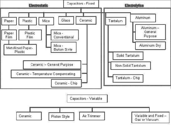
unique functional characteristics. The capacitors in this section are divided
into their technology categories as illustrated in Figure 1.
A general comparison between all capacitor styles is shown in Table 1,
and a more detailed comparison between the functional parameters of fixed
capacitor styles is shown in Table 2.
Note the numeric values given in Table 2
is for initial tolerance and stability after life testing for capacitors
manufactured to Military performance specifications. They may not be indicative
of similar commercial styles.
Frequency characteristics are
especially important when selecting a capacitor style. All capacitors have
frequency limitations due to the nature of the dielectric and other construction
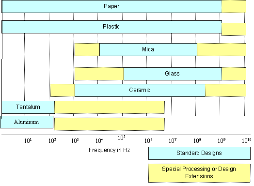
features. Figure 2
breaks down the frequency characteristics graphically. The frequency range of
electrolytics is the most difficult to describe because effective capacitance
involves a complex relationship between voltage rating, case size, nominal
capacitance value, and operating frequency. Alternating currents and operation
under pulse and energy storage conditions adds further complexities.
In addition to voltage rating, heat
dissipation must also be taken into account. Heat is generated as a result of
Equivalent Series Resistance (ESR), dielectric losses, and to a lesser extent,
by losses in the attachment of lead wires to the capacitor elements.

Figure 1. Capacitor
Technology Tree
Table
1. Summary of Application Characteristics by Capacitor Style
|
Capacitor Style
|
Application
Information
|
| Electrostatics |
|
| Fixed, Paper Film |
Low
cost, low reliability style available in medium capacitance values (0.001
mf
– 30 mf). Film/Foil capacitor style designed for
circuits requiring high insulation resistance, low dielectric absorption, and
where ac component of voltage is small.
Not intended for high humidity
applications. |
| Fixed, Plastic Film |
Broad class of capacitor style with similar failure
characteristics and modes but manufactured with different plastic Styles. Generally intended for high voltage
applications where the ac component of voltage is small in comparison to the dc
component. Same as above, except higher
in cost, higher in capacitance per volume, and less sensitive to environmental
conditions. |
| Fixed, Metallized Paper and Plastic |
Same as above, except the metallization process increases
voltmetric efficiency and provides self healing process at the expense of
decrease low impedance, low voltage performance. |
| Fixed, Mica, Conventional |
Low capacitance value, high frequency capacitor style intended
for use in circuits requiring precise filtering, bypassing, and
coupling. |
| Fixed, Mica-Button |
Small size, low capacitance value, high frequency style. Typical uses are in tuned circuits and in
coupling and bypassing high frequency applications. |
| Fixed, Glass |
Rugged, small size, low capacitance value style with good high
frequency characteristics and able to withstand high temperatures. Intended for applications where high
insulation resistance, low dielectric absorption, and fixed temperature
coefficients are important. |
| Fixed, Ceramic, General Purpose |
Small physical size capacitor with comparatively large
electrical capacitance and high insulation resistance. Intended for surface mount
applications. |
| Fixed, Ceramic, Temperature Compensating |
Intended to compensate for temperature induced variance from
other circuit elements. Used for highly
accurate circuits where change in capacitance value cannot be
tolerated. |
| Fixed, Ceramic, Chip |
Small size capacitor intended for surface mount
applications. Use where high accuracy
applications where variation in capacitance values with respect to temperature,
voltage, and life can be tolerated. |
| Electrolytics |
|
| Fixed, Tantalum, Chip |
Small size chip capacitor intended for relatively low voltage
surface mount applications. Intended for
similar applications as ceramic chip capacitors, but where higher voltmetric
efficiency is needed. |
| Fixed, Electrolytic, Tantalum, Solid |
Low frequency, high capacitance style. Primary application is power supply
filtering. Higher capacitive density,
but more expensive and higher leakage current than aluminum styles. Category covers both molded and dipped
styles. |
| Fixed, Electrolytic, Tantalum, Non-Solid |
High capacitance value capacitor, used primarily in low
frequency filtering applications.
Category covers plain foil, etched foil, and sintered slug capacitor
styles, each with unique functional characteristics. |
| Fixed, Electrolytic, Aluminum (General
Purpose) |
Most common electrolytic.
High capacitance density, high voltmetric efficiency, and low cost. Used primarily for low frequency
filtering. Not recommended for airborne
applications. |
| Fixed, Electrolyytic, Aluminum (Dry) |
High capacitance density, high volumetric efficiency, and low
cost style used primarily for low frequency filtering. Most common electrolytic. Not recommended for airborne
applications. |
| Variable |
|
| Variable, Ceramic |
Non-linearly adjustable, small sized trimmer capacitors
designed for applications where fine tuning is periodically required during the
life of equipment. |
| Variable, Piston |
Linearly adjustable, small sized trimmer capacitors designed
for applications where fine tuning is periodically required during the life of
equipment. |
| Variable, Air Trimmer |
Large capacitor intended for line rectification
applications. |
| Fixed-Variable, Gas/Vacuum |
Non-Linear variable capacitor intended for high power
applications. |
Table 2. Technical
Performance Characteristic Comparison of Various Capacitor Styles
| Characteristic |
Paper-Plastic |
Mica |
Glass |
Ceramic |
Tantalum |
Aluminum |
| Capacitance Range |
1pF to 50mF |
1pF to 90mF |
0.5pF to 20mF |
0.1pF to 1,000mF |
50pF to 1,200mF |
500pF to 200,000mF |
| DC Rated Voltage (v) |
30 to 2000 |
50 to 2,500 |
100 to 1,250 |
50 to 1,500 |
3 to 500 |
5 to 500 |
| Initial Tolerance |
±
0.5 to 20% |
±1
to 10% |
0.25pF to 5% |
±0.5pF
or 1% to 20% |
-5 to +75% |
-10 to +75% |
| Stability |
<2 to 10% |
<1 to 5% |
0.5% or 0.5pF |
3 to 20% |
<15% |
<15% |
| Relative Size for Equivalent CV
Rating |
Small to Large |
Large |
Large |
Fixed-Small Variable-Large |
Very Small |
Medium to High |
| Relative Cost for Equivalent CV
Rating |
Medium to High |
Medium |
Medium |
Low |
Very Small |
Medium |

Figure 2. Operating Frequency Limits of
Capacitors
|
|