Download the PDF file
Prepared for:
The Naval Surface
Warfare Center, Crane IN
29 September 2000
Prepared by:
Systems Design and
Analysis, Inc.
1398 North Shadeland Ave. suite 2235
Indianapolis, IN
46219-3619
www.sdaindy.com
This report is authorized under NSWC, Crane contract
N000164-98-D-0025, Delivery Order D0013, Paragraph 3.2(Task B).
This market investigation is primarily directed at
the identification of commercially available Spray cooling technologies which
could be used or adapted for use in cooling and/or heating Commercial Off the
Shelf (COTS) Electronic assemblies. Additionally, this investigation provides a
comparison of the various alternative cooling technologies and assesses their
applicability to the use of COTS in a military environment. The scope of this
investigation was general in nature due to cost and schedule limitations.
Task 1 Conduct a market
investigation of existing spray cooling technologies.
The market survey was conducted using the following
three approaches:
1. Discussions with experts in the field regarding
the use of dielectric liquids to cool electronics
2. A literature and file search for related
information
3. A detailed WEB search for information related to
spray cooling of electronics using dielectric liquids
Expert Knowledge
Discussions with experts in cooling research in the
academic community and experienced designers of cooling systems revealed that
significant basic research has been done in the area of dielectric liquid
cooling. Transfer of the research technology to commercial products has been
very limited. A recent SBIR (1996) effort involved comparison of dielectric
liquid cooling techniques. That effort included high heat flux liquid flow
through cooling, Spray Cooling and Jet Impingement cooling techniques applied to
practical military thermal management examples. SDA attempted to obtain copies
of the SBIR Phase II (N92-136) report detailing results. Re-organization of SBIR
offices and personnel has made it difficult to obtain the report. However, SDA
subcontracted with a long time associate that was the cognizant Navy technical
expert for that SBIR. His intimate knowledge of the SBIR efforts and 25 years
plus experience in the electronics cooling area was tapped for this market
survey. SDA also previously investigated dielectric liquid cooling research at
Purdue University, with specific interest in developing practical applications.
A foremost expert in the field at Purdue has been conducting research for over
15 years and has provided practical solutions to many commercial and government
customers such as CRAY Research, AT&T, IBM, and the US Air Force. It is
interesting to note that Purdue has been consulted numerous times regarding
Spray Cooling technology included as part of a larger system or product. SDA
refreshed the association with Purdue to obtain current research information.
Literature/ File Search
A literature/file search revealed some magazine
references to spray cooling and to Isothermal Research Systems (ISR) technology
development. It was also found that ISR previously received Phase I and II SBIR
funding for Change of Phase (COP) Spray cooling technology development. More
importantly, it was found that ISR was recently awarded a $35,000,000 contract
by the Naval Air Warfare Center Aircraft Division for the development of
airborne Spray Cooling systems.
Proceedings from the June 2000 DARPA sponsored
HERETIC Program Principal Investigators’ meeting were reviewed. The vision of
the HERETIC Program is “to develop micro-scale solid state and fluidic heat
removal devices that are integrable with dense electronics and optoelectronics
in order to short circuit the thermal resistance between the heat sources in the
electronics or optoelectronics devices and the thermal sinks.” Review of the
HERETIC material indicated a great deal of basic research is being conducted in
this area at Institutions such as MIT, Harvard, Stanford, and Carnegie Mellon
just to name a few. Other organizations such as the Jet Propulsion Laboratory
and Rockwell Science Center, LLC are participating. Virtually all of this work
involves basic research aimed at integrating cooling technologies with
semiconductor structures or subassemblies of semiconductors. Much of it is very
esoteric in nature. For example, one of the papers reviewed is titled Heat
Removal by Inverse Nottingham Effect with Heat Pipes. Practical applications
resulting from HERETIC Program research are years away.
WEB Search
To complete the market survey, a WEB search for
information on Spray Cooling technologies was conducted using a variety of
search words and terms to improve the chances of finding as much related
information as possible. The initial results of the search appeared to indicate
that a considerable amount of research on spray cooling has been reported by
academic sources such as Purdue University, the University of Kentucky, The
University of Minnesota, and the University of Maryland. Information indicated
that this research is basic in nature and that little or no commercial product
development work is in progress. Upon closer investigation, it was discovered
that no current web information could be found for University of Maryland
efforts. The University of Minnesota research web site dealt with Spray Cooling
techniques, but was very incomplete. A University of Kentucky web site did not
refer to current work that might be applicable, although it is believed that
Spray Cooling research was performed in recent years. ISR is known to have
worked with the University of Kentucky in the past. The Purdue University web
site was very complete and current, detailing extensive liquid cooling research
efforts and published papers.
Only one corporate WEB site was found with
significant spray cooling information, that of ISR. The ISR WEB site contained
extensive information on COP Spray Cooling, the ISR design approach, and the
firm’s experience with cooling COTS in a military environment. ISR equipment has
been under evaluation in the Marine Corp Advanced Amphibious Assault Vehicle
(AAAV) for some time. Discussions with company personnel have confirmed that, at
present, ISR is the only company known to be offering COP spray cooling
enclosures for use with COTS in a military environment.
Market Investigation Conclusions
The market investigation led to the following
conclusions:
1. The ISR technology is the only one known to be
directed at the cooling of low to medium power COTS electronics in a military
environment.
2. The ISR technology is the only one known to have
been evaluated by the military.
3. The recent large contract award to ISR by the U.S.
Navy indicates that ISR is the leader in commercially available spray cooling
technology and may be the only near term supplier of this technology.
Task 2 Provide a comparison of
spray cooling to other cooling technologies.
In conducting a comparison
of the various other cooling techniques to Spray Cooling it was decided that SDA
should identify potential COTS liquid cooling techniques and traditional methods
listing the advantages and disadvantages of each. That data is summarized and included as
Attachment 1.
A review of the
advantages and disadvantages of the cooling techniques in Attachment 1 leads to the immediate conclusion that almost any of
them could be the approach of choice in a particular situation. An example might be the direct immersion,
forced convection method to cool very high power density COTS electronics even
though this selection might be somewhat unique. It could very well be the only
feasible technical approach for a particular situation. In many cases, typical forced air cooling
will still be the method of choice.
Based on the recognition that military applications are varied, selection
of a particular technique as a single standard solution is not advisable. It
would be highly desirable have available a complete arsenal of possible
solutions and not focus on a “one size fits all” approach.
The SBIR efforts
previously mentioned can be summarized by saying that each technique examined is
appropriate in specific real world situations.
Purdue University compared three dielectric liquid cooling techniques;
Flow Through, Spray, and Jet Impingement. The Flow Through cooling technique
demonstrated heat removal capability of over 3000 Watts from a Standard
Electronic Module (SEM) Format E configuration (approx. 6” x 6”). The spray cooling technique demonstrated the
capability to cool a circuit card of SEM E size dissipating over 1000 Watts. The
Jet Impingement technique demonstrated cooling capability of over 5000 Watts on
a SEM E clamshell style circuit card.
Of particular interest to this investigation are the Spray
Cooling and Jet Impingement performance
results demonstrated by Purdue. Spray
Cooling offers good performance in applications with low to moderate heat
removal requirements. The individual
Spray Cooling components, such as nozzles, plumbing, pumps, filters, and heat
exchangers are commercially producible. However, it should be noted that special
machining capabilities are required to manufacture spray nozzles to the
precision and tolerance required. Purdue
research revealed variation in nozzle performance due to contamination,
corrosion, and long-term wear.
Placement of spray nozzles is fairly critical to assure adequate
cooling. A simplified drawing of the
Spray Cooling concept is shown in Figure 1.
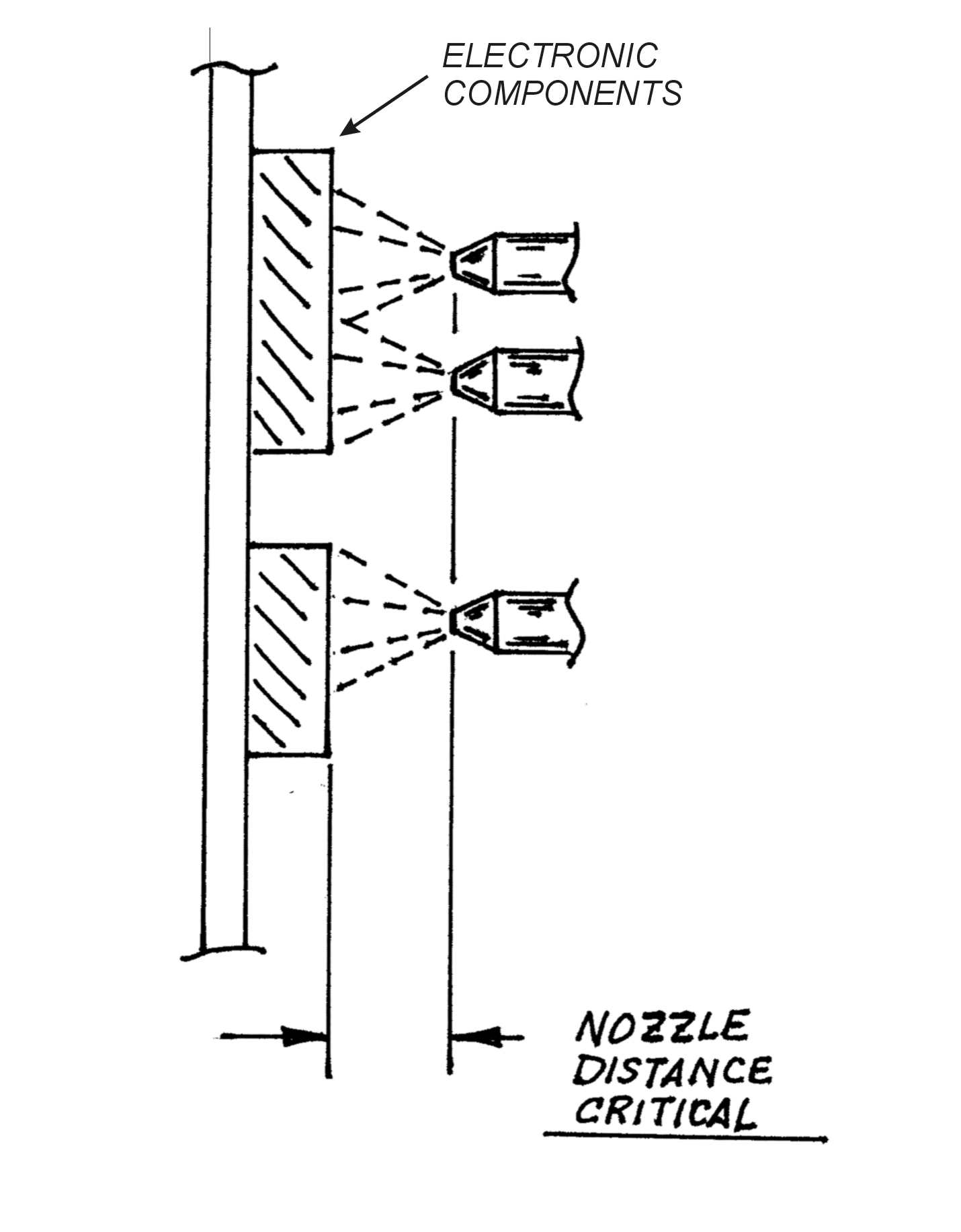
Figure 1. Spray Cooling Configuration
Example
Jet Impingement offers excellent cooling performance
in low to moderately high heat applications. Production of components is quite
easy because precision manufacturing is not required. A simple Jet Impingement
system could be constructed that delivers and directs dielectric liquid through
holes (nozzles) in a plate. Rectangular or circular shapes can be used and
tailored for size, flow rate, and velocity to match the heat dissipating
components. Precise positioning is not required. Purdue research found that
contamination, corrosion, and wear of Jet Impingement nozzles are of very little
concern, even though the dielectric fluid should be filtered and conditioned in
both Spray and Jet Impingement configurations. While no commercial product
currently exists using the Jet Impingement technique, it should be relatively
simple and low risk to develop and demonstrate a viable Jet Impingement cooling
system. A simplified drawing of the Jet Impingement concept is shown in
Figure 2.
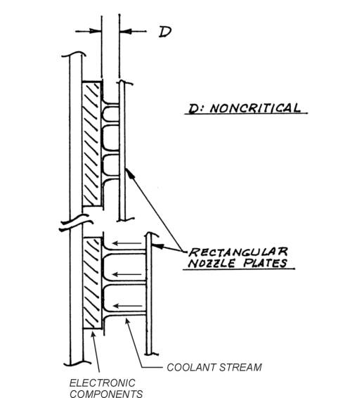
Figure 2. Jet Impingement Cooling
Configuration
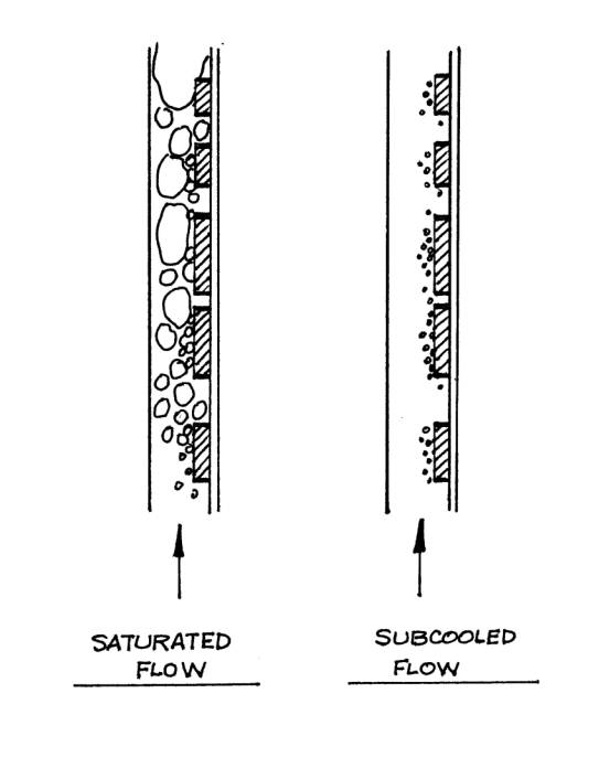
Figure 3. Direct Immersion and Flow
Through/Channel Flow Cooling
Two other interesting dielectric liquid cooling
concepts are presented here for information. Direct Immersion and Flow
Through/Channel Flow liquid cooling are alternatives to Spray or Jet Impingement
methods. An electronic package, such as a power supply, can be filled (Direct
Immersion) with a dielectric fluid that transfers heat from electronic
components to an external heat sink through conduction/convection. A larger
volume of fluid may be required depending on the size of the flow channel(s);
but nozzles, plumbing, a pump, and filter required by Spray or Jet impingement
methods are eliminated. A variation of Direct Immersion is a Flow
Through/Channel Flow configuration that directs coolant over the entire surface
of an electronic circuit card and components. Nozzles are not needed, plumbing
is minimized or eliminated, a pump circulates the coolant and a filter traps
contamination. Figure 3
shows bubbles generated by the COP action as heat is transferred from components
to the coolant. In the saturated flow example, large bubbles are generated.
Large bubbles may inhibit liquid contact with electronic parts; therefore
reducing heat transfer. This condition should be avoided. The subcooled flow
example illustrates the preferred situation where very small bubbles
(micro-bubbles) are produced by the COP actions that naturally condense back
into the bulk coolant flow. Subcooling is achieved exactly as the term implies.
The dielectric fluid is cooled some amount below the COP point based on the
specific system requirements. An important fact to note is that a variety of
dielectric fluids exist that can be mixed to achieve specific cooling
performance.
Cooling COTS systems in military environments is a
challenge that must be addressed by all military branches. COTS technology
brings the benefits of high performance at a low initial cost. However,
long-term cost of ownership may be high depending on reliability and
supportability. Developing appropriate cooling techniques will be a major factor
in the long-term viability of COTS technology in military applications.
This investigation confirmed that the only company
known to be doing commercial development work on Spray Cooling for COTS in
military applications and certainly the only company shipping operational Spray
Cooling systems is ISR. The fact that a market investigation was commissioned
indicates interest in liquid cooling technology exists within the Navy. SDA
experience confirms that cooling COTS equipment is recognized as a significant
part of successful development efforts. In the last 3 years SDA provided
engineering support to a Navy project to develop a commercial replacement for a
custom designed military system. Keeping the COTS electronics cool was a major
part of that effort. SDA has also discussed liquid cooling of COTS in extreme
environments with a military contractor. Other corporate or government
development work on Spray Cooling systems or liquid cooling was not discovered;
however, such work could be underway at firms under government contract with
highly restricted public access.
There is a risk in having only one supplier of liquid
cooling technology. Interruption of product supply, for any reason, can cause
large problems for military customers. One supplier that produces only Spray
Cooling equipment might not be able to handle peak demand periods or survive low
demand periods. Certainly, proprietary technology should be avoided. While
reliance on one technology or one supplier should be avoided, allowing a unique
solution for each system must be avoided. A balance between a mandated single
dielectric liquid cooling approach and many unique approaches should the goal of
the Navy.
Recommendations
1. Proceed with the evaluation of spray COP for use
as a general solution for cooling COTS. Spray COP is the most available advanced
cooling technique at this time and is applicable to situations where the use of
COTS is a necessity. It is the only technique with hardware available at this
time.
2. Do a feasibility study on the development and
demonstration of Jet Impingement COP cooling techniques to increase available
cooling options, cooling capacity, and augment Spray COP capabilities. Jet
impingement COP offers the potential for higher cooling capability and lower
manufacturing cost. It is also not a proprietary technology at this time.
3. Do a feasibility study on the development and
demonstration of Direct Immersion and Channel Flow COP cooling techniques to
offer solutions not provided by Spray Cooling or Jet Impingement. It is also not
a proprietary technology at this time.
4. Establish a second source for any liquid cooling
technology used or purchase all design rights and manufacturing documentation.
5. Monitor liquid cooling technology developments on
a regular basis.
|
|
Complexity
|
Availability
|
Effectiveness
|
Cost
|
|
Liquid Flow Through
|
|
|
|
|
|
|
|
|
|
|
|
Spray Cooling
|
|
|
|
|
|
Jet Impingement
|
|
|
|
|
|
Direct Immersion
|
|
|
|
|
|
Channel Flow
|
|
|
|
|
<align="center">COMPARISON OF
COOLING TECHNIQUES
APPLIED
TO COMMERCIAL PRODUCTS USED IN
MILITARY ENVIRONMENTS</align="center">
Introduction
Thermal Control, more
commonly know as cooling, is a critical engineering discipline that must be
successfully applied to ensure required performance and reliability in military
electronic systems constructed using commercial-off-the-shelf (COTS)
products. Studies performed during the
last 40 years investigating military electronic system failures indicate that
the majority were thermally related.
Electronic parts fail catastrophically from simple overheating or due to
a breakdown of components and attachment mechanisms brought on by thermal
cycling that causes excessive expansion/contraction of internal parts and
mounting substrates.
The prevention of catastrophic thermal
failure must be the primary goal of all electronic thermal management
schemes. Catastrophic failure can be
defined as the immediate, thermally induced total loss of electronic function in
a particular component or system. To
avoid electronic equipment failure, it is therefore essential to minimize the
thermally induced failure rates of each component comprising an electronic
system. The two main problems that must
be avoided are electronic components operating at elevated temperatures and
excessive thermal cycling. Each can act
independently to induce failure. In
concert they can act synergistically to assure premature failures in electronic
systems.
Mechanical/thermal engineers have spent untold hours
developing highly sophisticated electronic packaging to protect against the
effects of heat, cold, vibration, shock, electromagnetic radiation,
electromagnetic noise, and, corrosion to ensure survivability in severe military
environments. The requirement to use
COTS in military electronic systems offers many technological and performance
advantages but, in turn, causes incredible heartburn in packaging them in
ruggedized schemes so as to survive the same harsh environments as "classic"
military hardware did. While providing
relatively low cost and high electronic performance, COTS hardware is basically
fragile in environments other than relatively benign laboratory or industrial
environments. Providing proper
ruggedized protective packaging without turning enclosure systems into
overweight, complicated, and expensive boxes is a challenging task.
Potential Thermal Control Techniques for use
with COTS
Listed in ascending order of performance.
-
Natural air
convection
-
Forced air
convection
-
Module thermal
plane conduction to air or liquid convection heat exchangers
-
Radiation
-
Heat pipe
technology (very difficult to attach to COTS modules, either as tubes or as
"flat, shape-conforming plates")
-
Dielectric
liquids, e.g., non-CFC perfluorohexanes (3M Fluorocarbons), PAO (Coolanols),
Silicone oils.
Note: "Fluorocarbons" are the
much preferred dielectric liquids due to their safe performance
properties.
-
Direct
immersion natural convection [sensible and Change of Phase (COP)
mechanisms]
-
Direct
immersion forced convection (sensible and COP)
-
Spray
("atomized mist") COP
-
Jet impingement
COP
Note: Sensible in this context is a thermal
term defined as a non COP technique. It
is not intended to convey a good or bad comparison.
NATURAL AIR CONVECTION:
ADVANTAGES
-
Abundant, free supply
-
Requires no man-made pumping
mechanisms.
-
Minimal maintenance
-
No weight and volume impacts on
platform
-
Can be an open system, i.e.,
once used it can be dumped
-
Systems are
inexpensive
NATURAL AIR CONVECTION: DISADVANTAGES
-
Very low heat removal
capacity
-
Must have a gravity field
present for buoyancy action
-
May require
cleaning [foreign object debris, e.g., dirt, chemicals, fuel, etc, foreign
object debris (FOD)] and dehumidification
-
Performance is
adversely impacted by altitude. High altitudes severely reduce air molecular
density and heat capacity of the coolant air.
-
Equipment must be configured to
enhance natural flow "updraft."
-
Components must
be arranged to keep the flow from absorbing excessive heat from "lower"
components before reaching others that require substantial cooling.
-
All components
may not be reached by the air flow.
FORCED AIR CONVECTION:
ADVANTAGES
-
Abundant, free
supply if taken from atmosphere
-
Much more
efficient in heat removal than natural air convection.
-
May be taken
from turbine engine bleed air or other source and conditioned to a low
temperature.
-
Can be used in
open or closed systems.
-
No atmospheric
altitude impact if bleed air supplied
FORCED AIR CONVECTION: DISADVANTAGES
-
Engine bleed
air or other supply requires conditioning (throttling to lower temperature,
filtering, etc.).
-
Engine bleed
air or other supply may be limited, depending on how supply is prioritized to
other systems.
-
Requires more
complex pumping, ducting, and gasketing hardware. This adversely impacts platform weight,
volume, and structural fatigue life of platform.
-
Must be maintained
-
Atmospheric or "cabin" air may
require filtering to eliminate FOD.
-
Added weight
may require extra electronic system dynamics isolation if not hard
mounted.
-
Convection
surfaces must be free from debris and corrosion, to maintain convection
coefficients.
CONDUCTION: ADVANTAGES
-
May utilize
installation structures to reach an ultimate "heat sink" such as the ambient
environment or a large system/platform heat exchanger.
-
Module cards
may use attached thermal planes of aluminum, copper, Invar (heavy), or polymer-
or metal-matrix composite materials to transfer heat from components to other
locations such as conduction/convection heat exchangers.
-
Thermal planes
may be double-walled to pass a coolant.
-
Basic
conduction mechanisms require no extra pumps, ducting, filters, collection
reservoirs, etc.
-
May be
inexpensive unless more expensive materials are used. This in turn depends on cost of ownership and
reliability.
CONDUCTION: DISADVANTAGES
-
Requires high
pressure, intimate contact between heat transfer surfaces. This may require extra machining and surface
preparation, "thermal grease," other non-grease fillers.
-
Material thermal conductivity
dependant
-
Thermal paths
through multiple parts and surfaces will impose thermal resistances.
-
Transfer surfaces must be
maintained free of corrosion.
-
Transfer
surfaces must be free from vibration induced failures (separations leading to
more thermal resistance.
HEAT PIPE TECHNOLOGY
-
Heat pipes can
provide great thermal transfer through their liquid to vapor COP action; much
greater than conduction and air convection mechanisms. However, with respect to COTS electronics,
unless the modules are designed specifically to incorporate tubular or flat,
conforming hardware, they are not fiscally suitable.
RADIATION
-
Radiation is
not a good choice here either, as in a lot of "racked and stacked" electronic
systems. The very fact of close
proximity to other, equally dissipating (and receiving) units, will cause
minimal, if any, "net losses" of thermal energy.
DIELECTRIC LIQUIDS: ADVANTAGES, IN GENERAL
-
Can be used in
direct contact with electronic components, eliminating thermal path
resistances.
-
Can deliver
high heat transfer removal rates compared to air systems and conduction schemes
with high path resistances.
-
The
perfluorohexanes, i.e., "fluorocarbons" such as 3M Company Fluorinerts, are very
environmentally and "human" safe due to their inert, nontoxic, nonresidue, and
nonflammable nature.
-
Saturation
temperatures can be somewhat tailored to match component environment
requirements. this eliminates elevated
temperatures.
-
When used as
COP, component temperatures can be maintained reasonably constant. This eliminates thermal cycling.
-
Large
quantities are not necessarily required, thus avoiding excessive weight
(specific gravity for FC-72 =
1.62).
The following
considerations must be balanced when using an existing liquid or tailoring
one.
-
Cost/availability
-
Thermal
transfer properties
-
Specific
heat
-
Thermal
conductivity
-
Saturation
temperature and pressure (i.e., @ "boiling" COP
)
-
Freezing
temperature (pour point)
-
Viscosity
-
Density
-
Circulation
rates
-
Dielectric
strength
-
Inertness and
compatibility
-
Toxicity
-
Thermal
decomposition and impurities
-
Surface
tension
-
Moisture
effects
-
Pour and flash
points
-
Flammability
-
Oxygen displacement
DIELECTRIC LIQUIDS: DISADVANTAGES, IN
GENERAL
-
Not as good as
water for heat removal. At 70 - 80 F the specific heat of water at 70 - 80 F =
0.99Btu/LB while the specific heat of the fluorocarbons = approximately
0.25. However, water cannot be readily
used as a dielectric direct contact fluid.
-
Requires
complex hardware (especially for sprays with very critical nozzle dimensioning
and manufacture)
-
Cost can be
high, although continued use has caused reductions in cost.
-
Are heavier
than water. At specific gravity = 1.62
for FC-72, one gallon = approximately 13.2 pounds (assuming 8.2 lbs/gallon for
water). However note that huge
quantities are not necessarily required.
-
COP action
requires fluid reconditioning, i.e., temperature control, condensation,
etc.
DIRECT IMMERSION:
NATURAL CONVECTION, ADVANTAGES
-
Natural convection
requires no fluid moving hardware.
-
Direct contact
with parts
-
Can be used in either
sensible or COP methods.
-
See above
general advantages.
-
Can provide
close temperature control when used as COP.
-
See dielectric
liquid advantages.
DIRECT IMMERSION: NATURAL CONVECTION, DISADVANTAGES
-
Lowest heat
removal capability of the fluorocarbon mechanisms
-
Can be heavy,
depending on system volume.
-
See dielectric
liquid disadvantages.
DIRECT IMMERSION: FORCED CONVECTION, ADVANTAGES
-
Greater thermal
transfer than previous.
-
Direct contact
with parts.
-
With COP and Channel Flow COP, heat removal begins to exceed
other methods discussed previously and results in approximate constant part
temperatures. See above advantages.
-
When used as COP and
Channel Flow COP, subcooled inlet liquid can cause complete condensation of the
vapor micro bubbles within the bulk fluid flow, thus requiring conditioning only
a single phase liquid. This leads to a
more efficient mode of heat exchanger action and system operation.
-
More simple method
than spray and jet methods, yet affording high heat flux values.
-
See dielectric
liquid advantages.
DIRECT IMMERSION: FORCED CONVECTION,
DISADVANTAGES
-
Requires pumping
hardware and associated maintenance/cost.
-
Requires fluid
reconditioning.
-
Critical heat flux of the liquid coolant must be matched to the
system requirements to avoid exceeding nucleate boiling regime and leading to
overheating and catastrophic failure.
This is not necessarily a "disadvantage," just a design requirement.
-
See dielectric
liquid disadvantages.
SPRAY COP: ADVANTAGES
Previous
studies have indicated these advantages.
-
Can provide high heat
flux.
-
Gives good coverage
due to atomizing action.
-
May use less fluid
than forced convection, bulk flow mechanism.
-
May use
slightly less fluid than jet impingement.
SPRAY COP: DISADVANTAGES
Previous
studies have indicated these concerns.
-
Requires special
spray nozzles.
-
Requires complex fluid handling and reconditioning (condensation,
heat exchanger with ultimate "sink", etc) equipment. This adds weight and associated penalties to
platform systems.
-
Quality control is critical.
Studies have shown that the nozzles are very sensitive to manufacturing
tolerances and quality.
-
Nozzle action can
change in time due to erosion, corrosion build up, and contaminants.
-
Spray distance
to components is critical for development of "spray cone."
-
Spray velocity and momentum can be critical. If too great, it can lead to part erosion,
and splashing away without proper wetting of the part surfaces, leading to poor
cooling.
-
Proper distance and some degree of confinement has been found
necessary to avoid separation from surfaces, leading to poor wettability.
-
Must be used only as
COP. Has poor sensible cooling action
-
High pressure
required.
JET IMPINGEMENT COP: ADVANTAGES
Previous
studies have indicated these advantages.
-
Very high heat
fluxes can be achieved if desired.
-
Critically designed/manufactured nozzles not required. Plates with machined openings can be used.
-
Flow can be localized
if only a single jet is used.
-
Multiple jets placement is not as critical with respect to closeness
to/from parts.
-
Jet hardware is more repeatable and durable due to less precision
required in jet openings.
-
Will not splash and separate away from parts. There is no cone effect requiring specific
locations with respect to parts.
-
Thermal transfer can also take place in sensible regime better than
with spray. This could benefit overall
cooling and offer some redundancy.
JET IMPINGEMENT COP: DISADVANTAGES
Previous
studies have indicated these concerns.
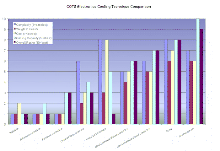
Cooling Technique
|
Cooling
Capacity
|
Complexity
|
Weight
|
Cost
|
Description/Comment
|
Overall
Rating
1=poor 10=excellent
|
|
Radiation
|
Low
|
Low
|
Low
|
Low
|
Does not allow
dense COTS card packaging. Very low cooling capacity.
|
1
|
|
Natural Air
Convection
(1)
|
Low
|
Low
|
Low
|
Low
|
Low cooling
capacity. Subjects COTS cards to heat, cold, humidity, salt, and contamination
of military environment.
|
1
|
|
Forced Air
Convection
(1)
|
Low
|
Low
|
Low
|
Low
|
Low to moderate cooling
capacity. Can be used in open or closed systems. Subjects COTS cards to heat,
cold, humidity, salt, and contamination of military environment.
|
3
|
|
Module Thermal
Plane Conduction to Heat Exchanger
|
Moderate
|
Moderate
|
Moderate
|
Moderate to
High
|
Requires custom
machined conduction planes for each COTS card. Moderate heat removal capacity.
Can be used in closed system.
|
3
|
|
Heat Pipe
Technology
|
Moderate
|
High
|
Moderate
|
Moderate to
High
|
Expensive and
very difficult to adapt to COTS cards.
Normally designed into card frame and enclosure structure.
|
1
|
|
Direct
Immersion
Natural Convection
|
Low to
Moderate
|
Low
|
Depends on type
and quantity of coolant fluid
|
Depends on type
and quantity of coolant fluid
|
Good heat
removal capacity. Technically simple. Cost and weight of coolant may be
problematic in some applications. Requires sealed enclosure. ILS issues may
exist.
|
6
|
|
Direct
Immersion
Forced Convection
|
Moderate to
High
|
Low to
Moderate
|
Depends on type
and quantity of coolant fluid
|
Depends on type
and quantity of coolant fluid
|
Very good heat
removal capacity. Cost and weight of coolant and fluid handling/reconditioning
equipment may be problematic in some applications. Requires sealed enclosure.
ILS issues may exist.
|
7
|
|
Spray
Change
of Phase (COP)
|
Moderate to
High
|
Moderate to
High
|
Depends on type
and quantity of coolant fluid
|
Moderate to
High
|
Very good heat removal capacity.
System contains special spray nozzles, fluid handling /reconditioning equipment,
and electronic controls. Requires sealed enclosure. Long term reliability
unknown. ILS issues may exist.
Most developed cooling
technique for COTS at present.
|
8
|
|
Jet
Impingement
Change of Phase (COP)
|
Moderate to
High
|
Moderate to
High
|
Depends on
type and quantity of coolant fluid
|
Low to
Moderate
|
Excellent heat removal capacity. System contains simple
spray nozzles, fluid handling/reconditioning equipment, and electronic controls.
Requires sealed enclosure. Potentially lower cost than Spray. High
reliability. ILS issues may exist.
Potentially the best system when fully developed.
|
8-10
|