Download the PDF file
References
AR 70-38, Research, Development,
Test and Evaluation of Materiel for Extreme Climatic Conditions, 1 Aug
79
MIL-STD-210, Climatic Extremes
for Military Equipment, 15 December 1973
MIL-STD-810, Test Method
Standard for Environmental Engineering Considerations and Laboratory Tests, 14
July 1989
EIA
Engineering Bulletin SSB-1, Guidelines for Using Plastic Encapsulated
Microcircuits and Semiconductors in Military, Aerospace, and Other Rugged
Environments
Background
To determine the reliability of equipment requires knowledge
of the stresses that the item will endure during its lifetime. The stresses include natural environments
(such as ambient temperature and humidity, solar radiation, atmospheric
radiation, atmospheric pressure), induced environments (such as vibration on
vehicle, handling drop shock, power dissipation heating, chemical exposure), and
operational duty cycle. Army Regulation
AR 70-38 and MIL-STD-210 define world-wide climactic extremes as well as typical
environmental conditions. MIL-STD-810
also addresses the natural environments in addition to induced
environments. A valid equipment system
specification will include the requirements for environments, duty cycle,
reliability, and useful life; however, often the system specification will not
provide specific life cycle environment profiles. The qualification requirements for the system
should address the anticipated life cycle exposure, such as that represented in Figure 1
,
but due to the complexity of a system and the asset value, the reliability
verification requires additional data from lower level testing on
sub-assemblies, components, and parts, so that the stresses experienced by these
elements requires characterization.
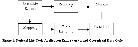
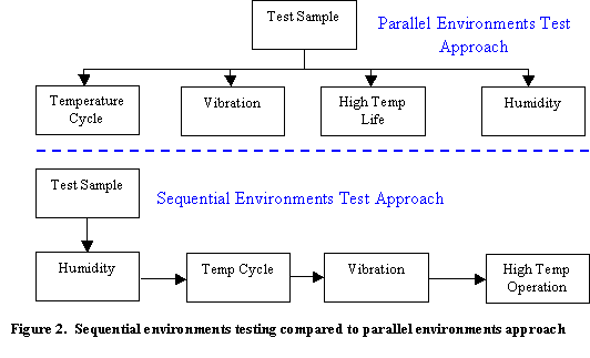
Figure 2 presents two common qualification test approaches applied at any particular
assembly level. The sequential
environments approach provides the best method of assessing the effects of life
cycle stresses, since it addresses cumulative degradation from the various
environments and operating conditions, as well as the potential synergies that
amplify the effect of a particular environment due to exposure to a previous
environment. The parallel test approach
cannot evaluate these synergistic effects, since it does not expose the product
to multiple environments.
Approach
The development of
qualification requirements for a part necessitates the understanding and
documentation of the anticipated life cycle environmental exposure and
operational duty cycle. Figure 1 depicts a generic typical life cycle scenario for a product. Each of the life cycle elements includes
environmental stresses and operational duty cycles that will consume some of the
useful life of the item. Some of these
environments induce synergistic effects, so that the order and combination of
stresses becomes important in overall effect on the product. These system level stresses will induce
possibly attenuated or amplified stresses at the part level. For instance, solar radiation and power
dissipation can elevate part temperatures far above the ambient temperature of
the system, yet the thermal mass of the system can attenuate temperature
changes.
Qualification
requirements for a part will typically include accelerated stress tests, since
the application requirements will specify lifetimes in excess of practical test
times. The use of accelerated test
conditions then require the use of degradation mechanism models to correlate
such conditions to actual use conditions.
To address the sequential and simultaneous stresses, the qualification
requirements must reflect the synergies of the various degradation mechanisms by
judicious ordering and combining of stresses.
The application of degradation models must address the range of possible
degradation mechanisms and associated model parameters to develop test times
that can detect degradation mechanisms with low acceleration factors. By proper ordering of sequential
environments, the superposition of the degradation effects can approximate the
actual use conditions. EIA SSB-1
provides a comprehensive summary of failure mechanisms that apply to plastic
encapsulated microcircuits (and can be extended to some other part and package
types) along with discussion on applying superposition of stresses to evaluate
life cycle reliability. The models in
SSB-1 do not address the degradation synergies of the various
environments.
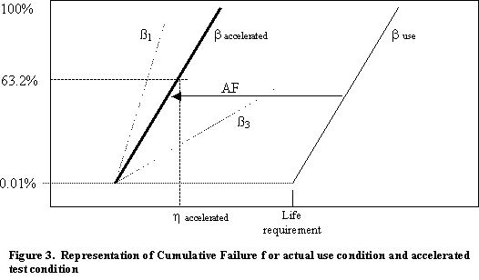
Figure 3 represents the cumulative failure distributions of the actual use and
accelerated test conditions using the Weibull distribution, where a particular
failure mechanism causes a cumulative failure distribution with Weibull slope,
b
actual, and 0.01% failing at the “life requirement.” Under accelerated stress, the failure
mechanism will cause a cumulative failure distribution shifted in time to result
in 0.01% failure at an earlier time, t accelerated. In general. the Weibull slope can be
different between the accelerated and actual use conditions (such as
ß1 and ß3), and only for the case where the use condition
time, tuse, is proportional to the accelerated condition time,
taccel, (e.g., tuse = AF*taccel, where AF is
the acceleration factor) will the slopes will be equal. A relatively generic transform of
tuse = AF*(taccel)n implies that buse
= baccel/n. With a large sample size, a test can
determine the time for a cumulative failure fraction of interest and then use
the acceleration model transform to determine when that particular cumulative
failure fraction will occur in actual use.
Sample size limitations often require assessment at a higher cumulative
failure fraction. In this case,
assumptions about the Weibull slope transform will impact the acceptance
criteria. The existence of multiple
failure mechanisms within a part with different acceleration factors under a
particular stress further complicates the development of acceptance criteria for
a sample test. Figure 4 shows the influence of activation energy,
Ea, assumptions on the acceleration factor for the Arrhenius model,
tfailure = Ae(Ea/kT), which provides an example of the
importance in assessing both the range of applicable model parameters for a
given failure mechanism (may depend on process control) and for accounting for
competing failure mechanisms in a given part.
The final test requirements must account for all of these concerns along
with the consumer and producer risks (i.e., the risk of accepting “bad” parts
and the risk of rejecting “good” parts).
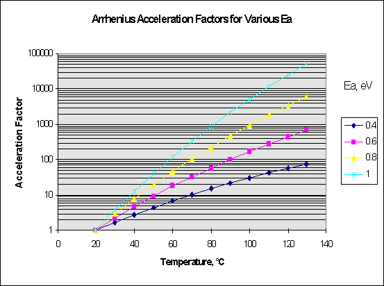
Figure 4.
Acceleration Factor dependence on activation energy for the Arrhenius
reaction rate model, showing large sensitivity to activation energy
assumptions
To determine appropriate test sample sizes
requires consideration of the intended failure rate, and the failure
distributions in both use and under accelerated conditions.
The simplest case involves mechanisms where the failure mechanisms have
the same shape, and represents the common assumption where both situations
result in an exponential (constant failure rate) distribution.
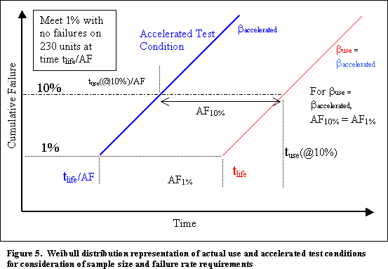
Consider a requirement that specifies less than 1% failure at
tlife.
A sample size of 230 units with no failures would provide 90% confidence
in meeting that requirement.
If test data on similar devices with the same failure mechanism exists to
show that an accelerated test can provide acceleration, AF, a test time on these
230 units of tlife/AF will assure meeting the requirement.
The representation in Figure 5
suggests that increasing the test time can accommodate a smaller test sample,
since longer test times allow sensitivity to larger cumulative failure
quantities.
In this case, using 10% cumulative failures as the performance measure
requires a longer test time, but fewer samples (i.e., a sample of 22 provides
90% confidence of fewer than 10% defective).
The uncertainty in the actual failure distribution poses the risk that
this assumption will result in improper characterization of the 1% failure point
of interest.
In addition, the general case with no similarity between the use and
accelerated condition failure distributions (e.g., different b
’s for the Weibull distribution, see Figure 3)
introduces uncertainty into the validity of the estimate that requires
assessment in the test development rationale.
Failure mechanism models often
only address the wear-out of properly assembled devices, and do not necessarily
relate to devices constructed with inadequate process control or materials. If the mainstream part capability greatly
exceeds the projected life requirement, the test specification may require
extension to verify the absence of process or material variations that cause
early failures in a small portion of the part population. For instance, evaluation of an application
requirement may indicate that 100 temperature cycles over a wide range equates
to the life cycle requirement, yet the general part qualification requirements
include 500 temperature cycles.
Summary
The qualification requirements
should account for the life cycle environments and duty cycle, as well as the
failure mechanism model parameter assumptions and the test sample size. The approach described herein provides a
generic approach for establishing qualification requirements for parts and
assemblies. Table 1 summarizes the step involved in developing the qualification
requirements.
| Table 1. Process for
Deriving Part Qualification Requirements Based on Life Cycle
Environments |
1. Define life cycle environments
(including duty cycle) at part level
2. Define part level reliability
expectation to meet system requirements
3. Identify failure mechanisms and
failure models applicable to part
4. Determine assembly process and material
variation impacts on part reliability
5. Identify synergistic effects of
environments on failure mechanisms
6. Determine sensitivity of models to
model parameter assumptions
7. Determine impact of failure distribution and
test sample size on test discrimination
8. Develop accelerated test
requirements that account for the above factors
9. Consider part capability
to provide sensitivity to process
variability |