
DASACON Conical Shock Tube
November 20, 2017
By: Dr. Jon Yagla
Special Guest Writer
In the early days of nuclear weapons testing, effects were studied by means of open detonations on land in New Mexico and at various remote sites in the Pacific Ocean. The testing released large amounts of radioactive material into the atmosphere, and as the health hazards became understood, the military and the Department of Energy (DOE) sought alternate means for testing. Underground test sites were built in Nevada where nuclear weapon performance was studied by detonations in tunnels and wells bored several thousand feet into bedrock and plugged with concrete. The shafts were only a few feet in diameter. Instrumentation with cables going to the surface provided weapon output data but could not provide blast effect data in the range of 0–100 psi (pounds per square inch) overpressure, the range of interest in weaponeering, target vulnerability, and hardening.
The Defense Atomic Support Agency (DASA), a DoD activity for nuclear weapons parallel to the DOE, which builds nuclear weapons, decided to build a conical shock tube large enough to test ship models and full-scale ship equipment items. Various trade studies were performed. It was decided to build a conical shock tube at Dahlgren with a diameter of 24 feet at the open end, and an increase of 1 foot of diameter per 100 feet of length, which works out to ½ mile long. The planned explosive charge was 1,000 pounds of TNT. With 25% efficiency, the device would simulate a blast from 40,000 pounds of TNT (20 tons) for every pound of TNT detonated at the apex. The apparent yield inside the tube would be 20 kilotons equivalent for a 1,000 pound charge, approximately the yield of the two weapons used near the conclusion of World War II.
The charge was confined at the apex in four 16-inch 50-caliber gun barrels placed end to end. The breech end and the first three barrels made up the heavy walled section of the gun barrels. The fourth barrel was full the 64 ft. length, making a 160 ft. long detonation chamber. Sleeves with a 16-inch inside diameter were manufactured to fill the barrels’ powder chambers and provide a continuous 16-inch diameter bore in the detonation chamber. This design was decided to be sufficiently risky to require preliminary tests to determine if the barrels could safely confine the detonation of TNT.
The idea was to use a cylindrical charge centered on the chamber axis. A test was set up at the Missile Test Facility using a 16-inch gun barrel with the breech closed and placed against a concrete block of size roughly 20 ft. x 20 ft. x 20 ft. The service pressure in the gun barrel with a powder charge was on the order of 40,000 psi, so the heavy wall portions of the barrels were considered safe. The [initial] test was performed by Dahlgren’s Wayne Culbertson from the Target Vulnerability Branch (TEV) in the Terminal Effects Division of the Warhead and Terminal Ballistics Laboratory. The branch head was Tom Truslow, the division head was Frank Kasdorf, and the department head was Dick Rossbacher.
Once the driver chamber concept was deemed safe, DASA awarded a contract to the American Machine and Foundry (AMF) Corporation to produce a detailed design of a “Conical Shock Tube Facility.” Internal pressure was a fundamental requirement for the design of the shock tube. AMF engineer Dr. Mario Balzerak performed a method of characteristics calculation on the internal pressure wave in the detonation chamber and its transition through an adapter section into the conical section.
Sun Ship and Dry Dock in Chester, PA was awarded the manufacturing and construction contract to build the Conical Shock Tube at Dahlgren in 1964 at a cost of $2,380,000. Construction was underway in 1965 and the facility was ready for testing in 1967.
A TEV group was established to support the shock tube, including:*
· Leon Anderson (physicist)
· Gary Blount (instrumentation engineer)
· Wellon Cole (instrumentation engineer)
· Joe Ebetts
· Jim McMahan (physicist)
· Jon Yagla (physicist)
Later, a Blast Effects Branch (TEB) was added, and included:*
· CDR Ernest Stavely (branch head during construction)
· Leon Anderson
· Wayne Culbertson (branch head during testing)
· Meade Corder (mathematician)
· Ned Donalson (mechanical engineer)
· Joe Ebetts
· Bernard Gardner (technician)
· Ray Harding (mechanical engineering technician)
· Glenwood Howland (technician)
· Ronald Hundley (engineering technician)
· Robert Jones (electrical engineering technician)
· Gary Kincaid (mechanical engineer)
· Kevin Mcardle
· Jim McMahan
· Alonzo Smith (electrical engineering technician)
· Art Terry (mechanical engineering technician)
· Jon Yagla
· Ethel Purks (secretary)
A contract was awarded to Wylie Laboratories for the facility’s instrumentation system. The instrumentation system was installed in the downstairs portion of Building 1104. The upstairs was eventually converted to office space for the branch. The instrumentation system was built to government specifications, and had equipment for monitoring 135 channels of high-frequency transient data. The data was cabled from sensors in the detonation chamber, tube sections, test sections, and test items to a patch panel in Building 1104. The system included signal conditioning units for piezoelectric, strain bridge, and thermocouple signals. The data was recorded by a bank of 14-track analog FM magnetic tape recorders during the test event, which only lasted about 2 seconds. The tapes were then played back through an analog-to-digital converter and input to a digital computer. The computer applied calibrations, scaled the data, and output each channel to a pen plotter. The data for a big test with 100+ channels of data could be processed and provided to the customer as engineering plots within a few days of the test. Selected channels could be provided immediately. It was truly a state-of-the-art system.
The shock tube recoil force was well up in the millions of pounds. The closed breech of the first gun was therefore connected to a recoil mass, over 3,000,000 pounds of reinforced concrete. This was done through a 12-inch diameter steel column about 10 ft. long. To load the TNT charge, the column was removed. A long trough, nicknamed the “hog trough,” was substituted for the column. A sewer bladder was installed in the transition section and inflated. The trough and driver chamber were filled with water to about the centerline. Cylindrical cast TNT charges were floated on Styrofoam™ trays into the chamber. Each segment was carefully taped to the one before it. The last charge was a short segment of booster charge that detonated the TNT. Charges up to 1000 lbs. were loaded into the chamber this way. The water was drained and the recoil column was positioned. Wage Grade (WG) ordnancemen did this work. The most industrious and hardest working of them was Blue Burgess.
Access to the test stations was through hatches over the stations. The hatches were unbolted and lifted by means of a railway crane that ran on railroad tracks parallel to the shock tube.
The calibration series began in earnest in the summer and fall of 1967, but there was a major snag in the course of the firings. After several successful shots producing the expected results, a shot was fired and about 700 ft. of the shock tube between test stations 2 and 3 collapsed. Yes, collapsed. When a positive going pulse arrives at a solid boundary, it reflects back as a positive pulse. However, if a positive pulse arrives at an open boundary, a positive pulse is transmitted into the surroundings and a negative pulse is reflected. The reflected wave at the end of the shock tube returned toward the apex as an expansion wave and reduced the pressure inside the tube to a value much lower than the pressure of the atmosphere. A cylinder loaded by external pressure is unstable and much weaker than when loaded by internal pressure of the same value. Atmospheric pressure crushed the tube. Yagla’s MS thesis at Arizona State University was “The Calculation of the wave reflected from the open end of a conical shock tube.” The pressure inside the tube as a traveling wave was calculated. Ned Donalson did engineering calculations to determine how to fix the tube. New sections were made and shipped to Dahlgren. Once they were installed in the shock tube, ring stiffeners were welded on at intervals calculated by Donalson. The tube was fixed and there weren’t any more problems. Oliver Huey designed a plate to put near the end of the tube to cancel the negative reflection with a positive reflection off the plate. The plate was supported on two railroad flat cars tied together side by side. When the next shot was fired, the plate folded back down onto the flat cars, but it worked, and the reflected wave was pretty much cancelled out. Yagla calculated the pressure load, and the plate was repaired and braced. It was called the reflection eliminator and was used in all remaining tests.
The calibration testing was finished and sufficient data obtained to calculate the explosive weight for any overpressure in any test station. Test blast overpressures up to 80 psi could be obtained in test station number 1, 45 psi in test station number 2, and 20 psi in test station number 3. The main Navy interest was in the lower pressures: less than 10 psi. Many items were tested, including a tethered model hovercraft (by Steve Miller), antennas, ship structures, and model buildings.
The first scientific test was an experiment to establish the detonation speed of the confined TNT charge and to assure the whole charge was consumed. Jon Yagla designed ionization probes, which were installed on the explosive segments as they were loaded into the chamber. The ionization was recorded at the arrival time of the detonation wave at each instrument. This signal was used to strobe and save the current state of a digital counter running at a high frequency. The results showed the detonation speed was not affected by the presence of the confinement and the charge was completely consumed. Pressure data confirmed the design calculations.
The most complex tests were done on missiles for the Safeguard Antiballistic Missile System. Leon Anderson designed complicated suspension systems to hold the missiles as free bodies in the shock tube. The missiles were Sprint (short range) and Spartan (long range). The missiles carried nuclear warheads and had to be able to fly through a nuclear blast created by the explosion of another nearby missile. The missiles were supported by harnesses made of 1-inch diameter nylon rope. Rope specimens were tested to determine the force deflection curve. Elaborate computer models were developed by Anderson, assisted by Bohdan Denysyk, to solve the equations of motion for the missiles responding to the blast loads. They sought ways of hanging the missiles and attaching tethers so the missiles could respond freely, and then be snubbed without contacting the test platform or shock tube wall. The tests were completely successful and provided valuable data to the Safeguard program. Phased array radars and hardened radar buildings for Safeguard were tested as well, and the test engineer was Glen Moore.
Navy testing in the shock tube was mainly for the Naval Ship Research and Development Center in Hyattsville, Maryland, and David Taylor Naval Ship Research and Development Center in Carderock, Maryland. At the time, the services hated each other almost as much as they hated the Russians. They just couldn’t work together on anything. The Air Force had to have its own test facility. Their nuclear weapons laboratory was at Kirkland AFB in Albuquerque, New Mexico. In conjunction with Sandia Corporation in Albuquerque, they built a nuclear blast simulator with three stepped cylinders, the largest 8 ft. in diameter. It was called the Thunderpipe. Other blast simulators with stepped cylinders were built by the Army in Aberdeen and foreign countries. Field trials with quantities of hundreds of tons of high explosive were carried out at White Sands Missile Range under DASA support (eventually the DASA name changed to Defense Nuclear Agency, which eventually became the present Defense Special Weapons Agency). Services and NATO allies shipped their equipment to White Sands and set it up at various distances from the charge. The agency paid for the charge and set up instrumentation recording equipment. The services paid for their own experiments and a share the instrumentation cost. It took several years to plan and conduct a single test. In this political climate, DASA and DNA could not get the name DASACON to stick to the conical shock tube. DASA said it had the right to the name it because it had funded it. The Navy said it’s ours now, and we want to call it the Conical Shock Tube Facility.
In comparison to other shock tubes at the time, the one at Dahlgren had a very clean pulse and was an almost perfect simulation of a nuclear blast pulse. Practically all the equipment tested in other shock tubes could have been tested at Dahlgren. Meanwhile, Dahlgren was mainly a test laboratory for the Bureau of Naval Weapons. The shock tube tests were all for BuShips. Dahlgren management was not happy with the technical benefit of our labor accruing to BuShips, and did not choose to invest money in developing the facility or equipment. Nor did they pursue funding from DNA to support or develop the capability. Meanwhile, the Naval Ordnance Laboratory in White Oak had ongoing work in the nuclear blast area sponsored by DNA. White Oak managed to get all the research money and actually used a lot of it to discredit the Conical Shock Tube.
Such a large facility with a large and complex instrumentation system needs a steady of flow projects to justify the staff of specialists required and perform routine maintenance, such as corrosion protection, maintenance of concrete foundations, and calibration of electrical equipment. Meanwhile nuclear warfare at sea seemed less and less likely. The former mandate for testing to meet nuclear blast requirements for ships and equipment was changed. Under the new rules, paper studies could be used instead of testing to meet the requirements.
With the insufficient flow of nuclear blast testing through the facility, other projects were carried out. A tragic mine explosion in Pennsylvania led to a large appropriation for mine safety studies and equipment. Robert VanDolah of the Bureau of Mines approached Dahlgren officials about the possibility of using the shock tube as a simulated mine. This led to an effort to first create mine explosions in the shock tube, then develop equipment to quickly sense and extinguish them. Key players in this effort were Lyle Johnson, Leslie Russel, and Joe Canfield, who were able to create coal dust explosions and extinguish them. They sensed the explosion with electronic equipment and dispensed purple-K into the flame to knock down the explosion.
The shock tube was also used to simulate a submarine in developing the Mk 50 torpedo warhead. Test station number three, 22 ft. in diameter, was used to simulate the interior of a submarine. The space was fitted out with shipboard equipment and manikins. Torpedo warheads were detonated just outside the test station and had to penetrate plate arrays, simulating submarine pressure hulls, to get into the interior simulated compartments.
The tests were sequentially numbered at the shock tube facility. In the summer of 1974, the Conical Shock tube was deemed to have completed its mission and was closed. Over 130 tests had been conducted. The shock tube fell into disrepair and was eventually sold as scrap metal.
*Please pardon any inadvertent omissions.
 |
 |
 |
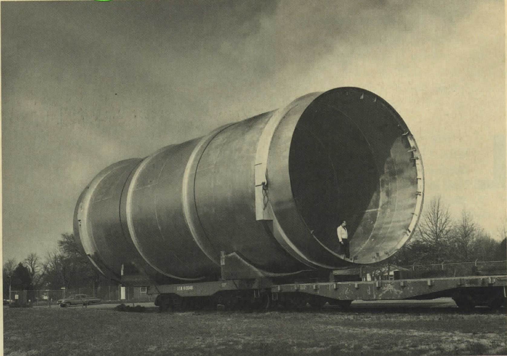
| A man stands in the muzzle of the conical shock tube during construction, c. 1967 |
Data acquisition and reduction equipment for the shock tube, in the basement of Building 1104.
|
Four million pounds of concrete were laid to absorb the recoil thrust of the shock tube. |